
ZW32-33/1250
Adopting advanced vacuum arc extinction technology, the breaker features excellent breaking performance and stable insulation. It supports long-term stable 1250A high-current full-load operation with arc-free, low-noise and pollution-free working status.
Equipped with a high-reliable spring operating mechanism, ZW32-33/1250 operates flexibly and stably with low mechanical wear. It can quickly cut off short-circuit faults and ensure safe and continuous power grid operation.
The fully sealed integrated structure is treated with professional outdoor anti-corrosion technology, featuring outstanding waterproof, dustproof and anti-aging performance. It adapts to high-altitude, humid and polluted harsh outdoor environments.
With compact structure and reasonable layout, the equipment is easy to install and debug on site. It requires minimal daily maintenance and effectively reduces long-term operation costs of power distribution projects.
As core high-current protection equipment for 33kV outdoor power systems, ZW32-33/1250 vacuum circuit breaker owns stable performance and high safety. We provide global customers with factory direct supply, complete certifications and professional after-sales service.
Product Details
1.1 Conditions of use
¨ Ambient air temperature: -30℃~+60℃;
¨ Altitude: no more than 3000 m;
¨ Wind speed not exceeding 34m/s;
¨ Vibration or ground motion from the outside of the switching device and control device is negligible;
¨ Pollution level: Ⅳ level;
¨ Storage temperature -40℃ ~ +85℃.
1.2 Technical parameters
Main technical parameters of circuit breaker
|
Order no. |
Item |
Unit |
Data |
|
1 |
Rated voltage |
kV |
33 |
|
2 |
Rated current |
A |
630/1250/1600 |
|
3 |
Rated frequency |
Hz |
50 or 60 |
|
4 |
Power frequency withstand voltage 1min (wet) (dry) Interphase, phase-ground/isolating distance |
kV |
80 95/95 |
|
5 |
Lightning shock resistant current (peak) Interphase, phase- ground/isolating distance |
kV |
185 |
|
6 |
Rated short circuit breaking current |
kA |
31.5/20/25 |
|
7 |
Rated short circuit closing current (peak) |
kA |
63/80 |
|
8 |
Rated peak withstand current |
kA |
63/80 |
|
9 |
4S short time withstand current |
kA |
31.5/20/25 |
|
10 |
Rated operating cycle |
|
O -0.1s-CO-3s- CO -6s CO-60s recovery |
|
11 |
Rated number of short circuit current breaks |
time |
30 |
|
12 |
Mechanical life |
time |
10000 |
|
13 |
Mechanism control voltage |
V |
AC/DC220 |
|
14 |
Secondary circuit 1min power frequency withstand voltage |
KV |
2 |
Main mechanical parameters of circuit breaker
|
Order no. |
Parameter name |
Unit |
Data |
|
1 |
Clearance between open contacts |
mm |
16±1 |
|
2 |
Contact overstroke |
mm |
3±0.5 |
|
3 |
Opening speed |
m/s |
1.4-1.8 |
|
4 |
Closing speed |
m/s |
0.4-0.8 |
|
5 |
Contact closing bounce time |
ms |
5 or less |
|
6 |
Center distance between phases |
mm |
460±2 |
|
7 |
Three phase open/close asynchronization |
ms |
2 or less |
|
8 |
Resistance of each phase circuit |
μΩ |
No isolation ≤80 isolation ≤150 |
|
9 |
Closing time |
ms |
100 or less |
|
10 |
Opening time |
ms |
50 or less |
|
11 |
Weight (300 without isolation, 380 with isolation) |
kg |
About 300-380 |
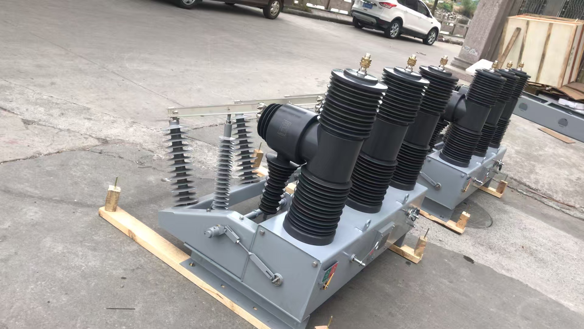
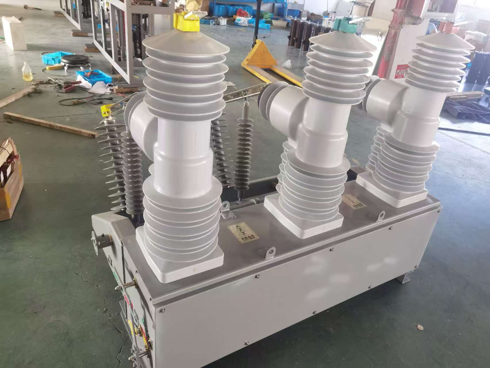
Circuit breaker structure and working principle
ZW32-33 outdoor high voltage vacuum circuit breaker is mainly composed of integrated fixed pole, current transformer, operating mechanism and box body. The circuit breaker is designed for miniaturization with high quality steel casing. Current transformer can be selected according to user's needs.
ZW32-33 outdoor high voltage vacuum circuit breaker matches with intelligent control combination. The switch can be operated locally or remotely through the communication interface. Other information of circuit breaker can also be transmitted to the control center, communication channels can choose cable, optical fiber, GPRS/CDMA, GSM and so on.
3 Working principle of circuit breaker
3.1 Arc extinguishing principle: ZW32-33 outdoor high-voltage vacuum circuit breaker adopts a vacuum arc extinguishing chamber and uses vacuum as the arc extinguishing and insulating medium, which has a high vacuum degree. When the dynamic and static contact open in charged condition under the action of operating mechanism, it will produce a vacuum arc between the contact, at the same time, due to the special structure of the contact, in the clearance of contact it also can produce appropriate longitudinal magnetic field, prompting vacuum arc is diffusion model, and it makes the arc evenly distributed on the surface contact burning, maintaining low electric arc voltage, when the current naturally passes zero, the residual ions, electrons and metal vapor can compound or condense on the contact surface and the shield cover in the order of microseconds, and the dielectric insulation strength of the arc extinguishing chamber is restored quickly, so that the arc is extinguished to achieve the purpose of breaking. Since the vacuum arc is controlled by longitudinal magnetic field, the vacuum circuit breaker has a strong and stable breaking current capacity.
3.2 Electric energy storage: the motor applies the output torque on the pinion of the mechanism and drives it to the large sprocket on the main shaft, thus driving the crank to rotate and making the closing spring energy storage. When the screw on the crank down stroke switch, cut off the motor power, spring energy storage.
3.3 Manual energy storage: the output shaft of the rotating mechanism transmits the rotating torque to the large gear which is fully meshed with the pinion through the pinion on the output shaft, thus driving the crank to rotate and making the closing spring energy storage.
3.4 Closing electromagnet operation: after the mechanism receives the closing signal, the moving core of the closing electromagnet moves upward, pushing the closing tripper lever to move upward and making the closing half axis rotate counterclockwise. Release the constraint on the closing pawl, at the same time, the closing pawl by roller pressure and counterclockwise rotation, remove the energy storage maintenance, the CAM located on the main axis due to the closing spring contraction force produces an impact force, hit the manual energy storage shaft (output shaft) on the rocker arm, through the connecting rod drive to switch, so as to complete the closing operation.
3.5 Manual operation: when the shifting fork installed on the closing axle rotates counterclockwise, it will drive the closing axle to rotate counterclockwise. The result is the same as the closing electromagnet operation.
3.6 Reclosing operation: after releasing the energy of the energy storage spring, the mechanism completes the closing operation. In the closing state, the mechanism carries out the energy storage operation. After the completion of the energy storage operation, the mechanism is in the closed state of energy storage.
3.7 Operation of opening electromagnet: when the mechanism receives the opening signal, the moving core of the opening electromagnet moves upward, pushing the opening release rod to move upward and making the half axis of the opening rotate counterclockwise. Unbind the opening gate gate. At the same time, the opening release is counterclockwise rotating under the pressure of the roller, and the rocker arm is counterclockwise rotating due to the thrust of some opening springs in the switch, thus completing the opening release operation.
3.8 Manual operation: when the fork installed on the opening half shaft rotates counterclockwise, it will drive the opening half shaft to rotate counterclockwise, thus producing the same effect as the operation of the opening electromagnet.
3.9 Overcurrent trip operation: when the overcurrent coil in the overcurrent trip device passes the prescribed trip current, the electromagnet moves and the push rod moves the trip rod. Make the half-axis of the breaker rotate counterclockwise and release the constraint on the opening pawl so as to produce the same effect as the operation of the opening electromagnet and complete the overcurrent trip operation of the breaker.

Online Inquiry
Or use the inquiry form below. Our sales staff will contact you within 24 hours. Thank you for your interest in our products!